Export Control
EAR Export Classification: Not subject to the EAR per 15 C.F.R. Chapter 1, Part 734.3(b)(3), except for the following Service Bulletins which are currently published as EAR Export Classification 9E991: SBE70-0992, SBE72-0483, SBE72-0580, SBE72-0588, SBE72-0640, SBE73-0209, SBE80-0024 and SBE80-0025.Copyright
© IAE International Aero Engines AG (2001, 2014 - 2021) The information contained in this document is the property of © IAE International Aero Engines AG and may not be copied or used for any purpose other than that for which it is supplied without the express written authority of © IAE International Aero Engines AG. (This does not preclude use by engine and aircraft operators for normal instructional, maintenance or overhaul purposes.).Applicability
All
Common Information
TASK 72-41-22-200-005 HPC Stage 11 Stator Vane - Examine, Inspection-005
Effectivity
FIG/ITEM | PART NO. |
|---|---|
06-150 | 6A3415 |
06-150 | 6A4241 |
06-150 | 6A7498 |
06-200 | 6A3413 |
06-200 | 6A4238 |
06-200 | 6A7499 |
06-200 | 6A8789 |
06-250 | 6A3414 |
06-250 | 6A4239 |
06-250 | 6A7500 |
06-250 | 6A8790 |
06-350 | 6A3416 |
06-350 | 6A4240 |
06-350 | 6A7501 |
06-350 | 6A8791 |
06-400 | 6A3277C01 |
06-400 | 6A4237C01 |
06-400 | 6A7502C01 |
06-400 | 6A8787 |
06-448 | 6A3277C01 |
06-448 | 6A4237C01 |
06-448 | 6A7502C01 |
06-448 | 6A8787 |
06-450 | 6A3277C02 |
06-450 | 6A4237C02 |
06-450 | 6A7502C02 |
06-450 | 6A8788 |
General
This TASK gives the procedure for the inspection of the HP compressor stage 11 stator vanes.
Nicks and dents 0.005 in. (0.13 mm) or less are acceptable without limit to the airfoil and gas washed surfaces of the platforms.
Fig/item numbers in parentheses in the procedure agree with those given in the IPC. Only the primary Fig/item numbers are used. For the service bulletin alpha variants refer to the IPC.
The policy that is necessary for inspection is given in the SPM TASK 70-20-01-200-501.
All the parts must be cleaned before any part is examined.
All the parts must be visually examined for damage, corrosion and wear. Any defects that are not identified in the procedure must be referred to IAE.
The procedure for those parts which must have a crack test is given in Step. Do the crack test before the part is visually examined.
Do not discard any part until you are sure there are no repairs available. Refer to the instructions in repair before a discarded part is used again or oversize parts are installed.
Parts which should be discarded can be held although no repair is available. The repair of a discarded part can be shown to be necessary at a subsequent date.
All the parts must be examined to make sure that all the repairs have been completed satisfactorily.
The practices and processes referred to in the procedure by the TASK/SUBTASK number are in the SPM.
References
Refer to SPM for data on these items:
Definition of Damage, SPM TASK 70-02-02-350-501,
Inspection of Parts, SPM TASK 70-20-01-200-501.
Some data on these items is contained in this TASK. For more data on these items refer to the SPM:
Methods of Testing for Crack Indications,
Chemical Processes,
Surface Protection.
Preliminary Requirements
Pre-Conditions
NONESupport Equipment
NONEConsumables, Materials and Expendables
NONESpares
NONESafety Requirements
NONEProcedure
Clean the parts. Refer to TASK 72-41-22-100-000 (CLEANING-000).
Refer to Step.
Airfoil tips.
Cracked.
Do the test for cracks on the parts that are given below.
PART IDENT
TASK/SUBTASK
Stage 11 Stator Vanes
SUBTASK 72-41-22-230-055 Examine the Stage 11 Stator Vanes for Cracks
Reject.
NOTE
A Tallysurf measuring instrument must not be used.
More than the Step.
Nicked.
NOTE
A Tally surf measuring instrument can be used, however, it is overhaul shops decision on the equipment they choose.Reject.
More than in Step.
Dented.
Repair, VRS6084 TASK 72-41-22-300-018 (REPAIR-018).
More than Step.
Examine the surface finish of the vanes. Use 10 percent of the vanes that have been removed.
SUBTASK 72-41-22-220-092-001 Examine the Stage 11 Stator Vanes Concave and Convex Airfoil Surfaces at Locations 1 and 2, (06-150, 06-200, 06-250, 06-350, 06-400, 06-448 and 06-450, 6A3415, 6A3865, 6A4241, 6A3413, 6A3801, 6A4238, 6A3414, 6A3802, 6A4239, 6A3416, 6A3803, 6A4240, 6A3277C01, 6A3804C01, 6A4237C01, 6A3277C01, 6A4237C01, 6A3277C02, 6A3804C02 and 6A4237C02) (Pre SBE 70-0714 and SBE 70-0726)
Reject.
More than the Step.
Nicked
Reject.
More than in Step.
Dented.
Repair, VRS6084 TASK 72-41-22-300-018 (REPAIR-018)
More than Step.
Surface finish.
SUBTASK 72-41-22-220-092-002 Examine the Stage 11 Stator Vanes Concave and Convex Airfoil Surfaces at Locations 1 and 2 (SBE 70-0714 and SBE 72-0561)
Refer to Figure.
SUBTASK 72-41-22-220-093 Examine the Stage 11 Stator Stop Vanes Stop Slot at Location 3
SBE 70-0714: Announcement of super polished HP Compressor Blades and Vanes.
SBE 70-0726: Announcement of HP Compressor Blades and Vanes without super polished finish.
SBE 72-0561: Engine- HP Compressor - V2500 Selectone Production- HP Compressor upgrade.
Refer to Figure.
Accept.
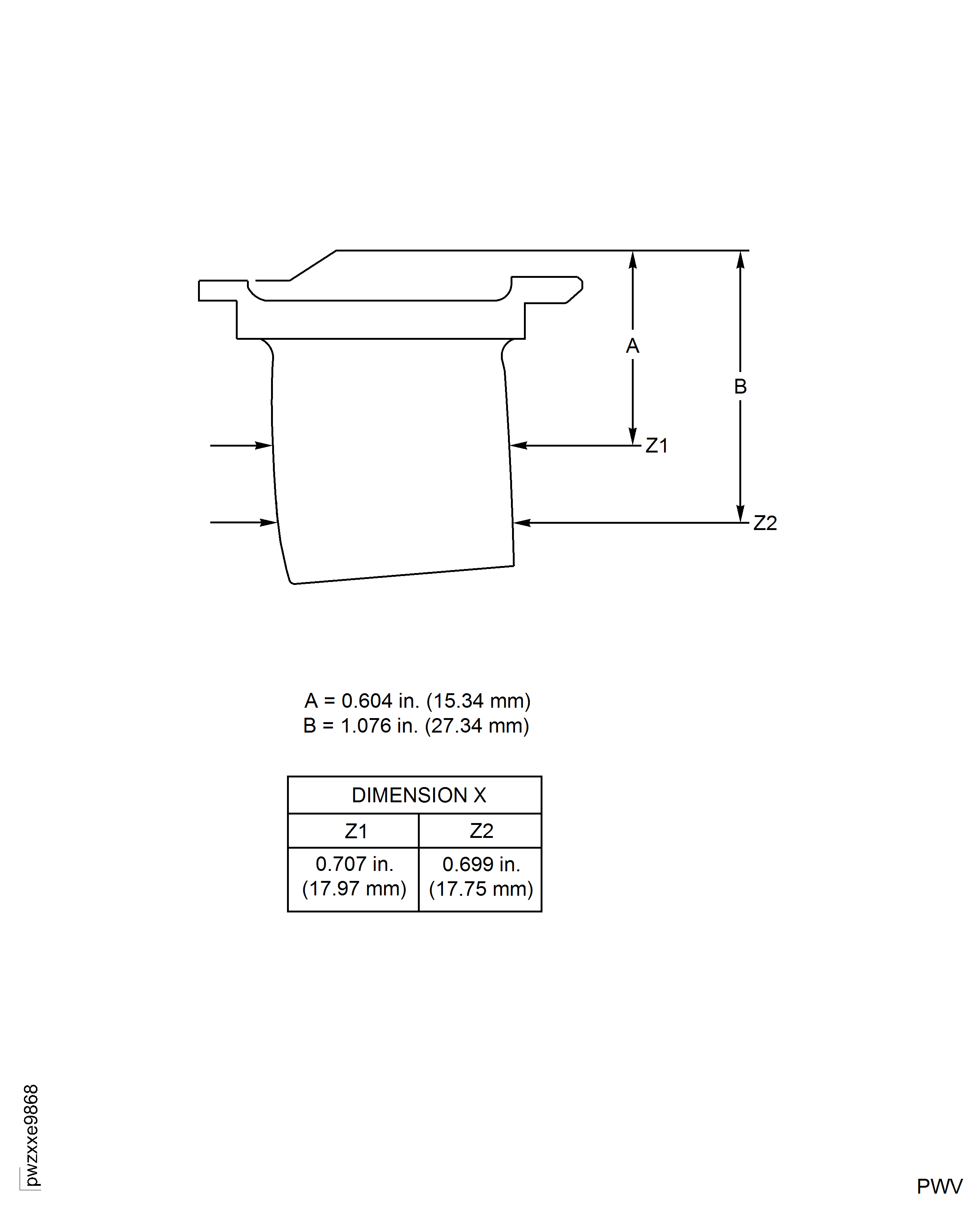
Minimum chord for Z1 and Z2 at the heights A and B not less than value X.
Reject.
Less than value X.
SUBTASK 72-41-22-220-219 Examine the Stage 11 Stator Vanes Chordal Width (A5 only) (pre SBE 70-0714, SBE 70-0714, SBE 70-0726 and SBE 72-0561)
Refer to Figure.
SUBTASK 72-41-22-220-096 Examine the Stage 11 Stator Vanes Faces at Locations 8 and 9
Repair, VRS6064 TASK 72-41-22-300-020 (REPAIR-020) or Repair, VRS9535 TASK 72-41-22-300-026 (REPAIR-026).
Cracked
Accept.
Within limits in TASK 72-41-00-040-001-A00.
Repair, VRS6064 TASK 72-41-22-300-020 (REPAIR-020) or Repair, VRS9535 TASK 72-41-22-300-026 (REPAIR-026).
Identified with radius beyond min value in TASK 72-41-00-040-001-A00 or vanes not part of a set.
Rubbed
SUBTASK 72-41-22-220-114 Examine the Stage 11 Stator Vanes Airfoil Tips at Location 1061 for Cracks
More than Step.
Surface finish.
Refer to SPM TASK 70-35-03-300-501 to remove score
On face edge
Scored/Scratched.
Reject.
More than the Step.
Nicked.
Reject.
More than in Step.
Dented.
SUBTASK 72-41-22-220-218 Examine the Stage 11 Stator Vanes Platform (Annulus Surface) at Location 18 (SBE 70-0714 and SBE 72-0561)
NOTE
Class identification marks as scores.Refer to SPM TASK 70-35-03-300-501 to remove score
On face edge
Part marking and repair symbol location 19.
Refer to SPM TASK 70-35-03-300-501 to remove score
On face edge
Examine the stage 11 stator vane at location 20.
SUBTASK 72-41-22-220-240 Examine the Stage 11 Stator Vanes Platform (Bottom Face)
More than in Step.
Nicked, dented or scored/scratched.
SUBTASK 72-41-22-220-116 Examine the Stage 11 Stator Vanes all Remaining Surfaces
Figure: Stage 11 Stator Vanes - Inspection Locations
Sheet 1

Figure: Stage 11 Stator Stop Vanes - Inspection Locations
Sheet 2

Figure: Stage 11 Stator Intrascope Vanes - Inspection Locations
Sheet 3

Figure: Stage 11 Stator Vanes - Inspection Locations
Sheet 4

Figure: Stage 11 Stator Vanes - Inspection Locations
Sheet 5

Figure: Stage 11 Stator Vanes - Chordal Width Locations and Limits