Export Control
EAR Export Classification: Not subject to the EAR per 15 C.F.R. Chapter 1, Part 734.3(b)(3), except for the following Service Bulletins which are currently published as EAR Export Classification 9E991: SBE70-0992, SBE72-0483, SBE72-0580, SBE72-0588, SBE72-0640, SBE73-0209, SBE80-0024 and SBE80-0025.Copyright
© IAE International Aero Engines AG (2001, 2014 - 2021) The information contained in this document is the property of © IAE International Aero Engines AG and may not be copied or used for any purpose other than that for which it is supplied without the express written authority of © IAE International Aero Engines AG. (This does not preclude use by engine and aircraft operators for normal instructional, maintenance or overhaul purposes.).Applicability
All
Common Information
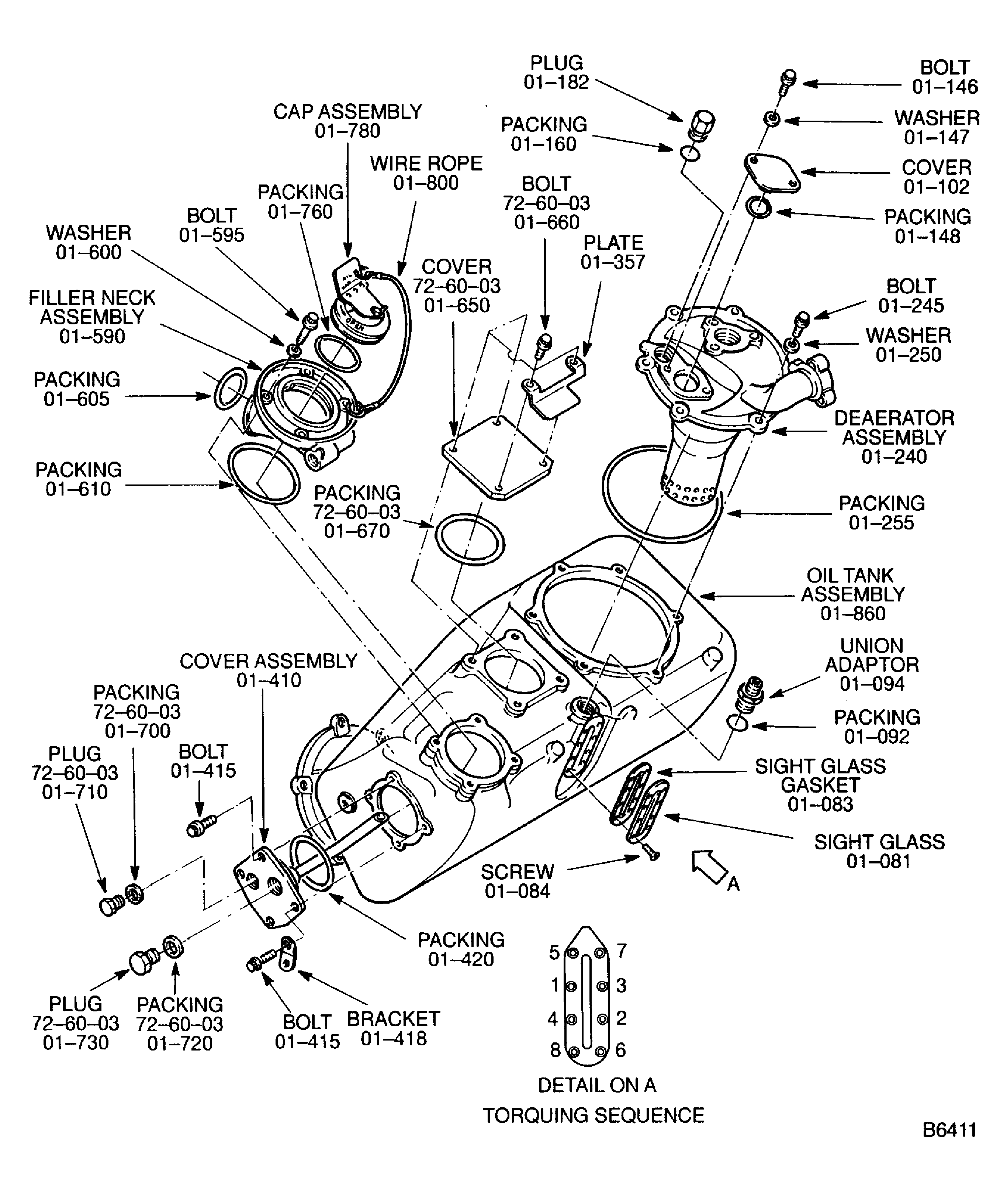
TASK 79-11-41-460-401-B00 Oil Tank - Related Parts - Assemble The Oil Tank, Assembly-001
General
Fig/item numbers in parentheses in the procedure agree with those used in the IPC. Only primary Fig/item numbers are used. For the service bulletin alpha variants refer to the IPC.
Transportation covers/blanks must be removed immediately before the installation of the components.
Refer to the V2500 Illustrated Tool and Equipment Manual (ITEM), Pub. ref. ITE-V2500-1IA, for the illustrations of the special tools given in this procedure.
Lubricate all threads and abutment faces of nuts and bolts with approved engine oils, unless other lubricants are referred in the procedure. For the approved engine oils and procedures, refer to SPM TASK 70-64-00-640-501.
To identify, lubricate and install seal rings, refer to SPM TASK 70-64-02-640-501.
For standard torque data and procedures refer to SPM TASK 70-41-00-400-501.
Special torque data and assembly tolerances are included in the procedure.
For lockwire data and procedures refer to SPM TASK 70-42-05-400-501.
After assembly repair any damaged surfaces protection, joint flanges and attach parts. Refer to SPM TASK 70-38-02-100-501.
NOTE
NOTE
Expendable parts
FIG/ITEM | PART IDENT | QTY |
|---|---|---|
72-60-03, 01-670 | Packing | 1 |
72-60-03, 01-700 | Packing | 1 |
72-60-03, 01-720 | Packing | 1 |
79-11-41, 01-083 | Sight-glass gasket | 1 |
79-11-41, 01-092 | Packing | 1 |
79-11-41, 01-140 | Packing | 1 |
79-11-41, 01-148 | Packing | 1 |
79-11-41, 01-160 | Packing | 1 |
79-11-41, 01-255 | Packing | 1 |
79-11-41, 01-420 | Packing | 1 |
79-11-41, 01-605 | Packing | 1 |
79-11-41, 01-610 | Packing | 1 |
79-11-41, 01-760 | Packing | 1 |
Preliminary Requirements
Pre-Conditions
NONESupport Equipment
| Name | Manufacturer | Part Number / Identification | Quantity | Remark |
|---|---|---|---|---|
| IAE 1F10082 Guide Pin | 0AM53 | IAE 1F10082 | 2 |
Consumables, Materials and Expendables
| Name | Manufacturer | Part Number / Identification | Quantity | Remark |
|---|---|---|---|---|
| CoMat 02-141 LOCKWIRE | LOCAL | CoMat 02-141 |
Spares
NONESafety Requirements
NONEProcedure
Install the Oil Tank to suitable support.
SUBTASK 79-11-41-470-051 Install the oil Tank Assembly to Suitable Support
Refer to Figure.
Install OIL-OIL TANK (79-11-41, 01-420) packing on the cover assembly.
Install the IAE 1F10082 Guide Pin into the bolts holes on the cover assembly attaching boss. Install the pins in opposite position.
Install the cover assembly to the boss, with the outlet tube turned to the top.
Remove the IAE 1F10082 Guide Pin.
Install the bracket OIL-OIL TANK (79-11-41, 01-418) with the bolt to the cover assembly.
Install the remaining three bolts.
Torque the four bolts to 85 lbfin to 95 lbfin (9.604 Nm to 10.734 Nm).
SUBTASK 79-11-41-470-066 Install the Cover Assembly (01-410) and the Bracket (01-418)
Refer to Figure.
Install Transportation Fittings (72-60-03, 01-700) packing on the plug groove Transportation Fittings (72-60- 03, 01-710).
Install Transportation Fittings (72-60-03, 01-720) packing on the plug groove Transportation Fittings (72-60- 03, 01-730).
Install the two plugs in their seats on the cover assembly. Torque the plugs to 53 lbfin to 71 lbfin (6 Nm to 8 Nm).
Safety the plugs together with CoMat 02-141 LOCKWIRE.
SUBTASK 79-11-41-470-067 Install the Plugs (72-60-01, 01-710) and (72-60-03, 01-730) to the Cover Assembly
Refer to Figure.
Install OIL-OIL TANK (79-11-41, 01-255) packing on the deaerator assembly groove.
Install the IAE 1F10082 Guide Pin into the bolts holes on the deaerator assembly attaching boss. Install the pins in opposite position.
Install the deaerator assembly to the boss, with the oil scavenge tube mating flange tuned to the starboard side of the tank. Align the boltholes with the guide pins.
Remove the IAE 1F10082 Guide Pin.
Attach the deaerator assembly with the six bolts and washer. Torque the bolts to 85 lbfin to 95 lbfin (9.604 Nm to 10.734 Nm).
SUBTASK 79-11-41-470-068 Install the Deaerator Assembly (01-240)
Refer to Figure.
Install OIL-OIL TANK (79-11-41, 01-148) packing on the cover.
Install the IAE 1F10082 Guide Pin into the bolts holes of the cover attaching boss.
Install the cover to the deaerator assembly and the bracket on the cover.
Remove the IAE 1F10082 Guide Pin.
Install the two bolts. Torque the bolts to 85 lbfin to 95 lbfin (9.604 Nm to 10.734 Nm).
SUBTASK 79-11-41-470-069 Install the Cover (01-102)
Refer to Figure.
Install OIL-OIL TANK (79-11-41, 01-160) packing on the plug.
Install the plug to the deaerator assembly. Torque the plug, to 53 lbfin to 71 lbfin (6 Nm to 8 Nm).
SUBTASK 79-11-41-460-070 Install the Plug (01-182)
Refer to Figure.
Install Transportation Fittings (72-60-03, 01-670) packing on the cover.
Install the IAE 1F10082 Guide Pin into the boltholes on the cover attaching boss.
Install the cover to the boss. Align the boltholes with the guide pins.
Remove the IAE 1F10082 Guide Pin.
Position the plate on the cover. Align the boltholes.
Attach the cover and the plate with the four bolts. Torque to 85 lbfin to 95 lbfin (9.604 Nm to 10.734 Nm).
SUBTASK 79-11-41-460-071 Install the Plate (01-357) and the Cover (72-60-03, 01-650)
Refer to Figure.
Install OIL-OIL TANK (79-11-41, 01-605) packing and OIL-OIL TANK (79-11-41, 01- 610) packing on the filler neck assembly.
Install the IAE 1F10082 Guide Pin into the boltholes on the filler neck assembly attaching boss.
Install the filler neck assembly to the boss with the filler neck port pointed outboard of the oil tank assembly. Align the boltholes with the guide pins.
Remove the IAE 1F10082 Guide Pin.
Attach the filler neck assembly with the four bolts. Torque the bolts to 85 lbfin to 95 lbfin (9.604 Nm to 10.734 Nm).
SUBTASK 79-11-41-470-072 Install the Filler Neck Assembly (01-590)
Refer to Figure.
Install OIL-OIL TANK (79-11-41, 01-760) packing on the cap assembly.
Align the lock of the cap assembly with the two slots on the filler neck port and install it.
Turn the handle of the cap assembly clockwise until it stops.
Lower the handle of the cap assembly from open to close position.
Attach the two connecting rings of the wire rope assembly OIL-OIL TANK (79-11-41, 01-800) to the holes in the cap assembly and in to the filler neck assembly.
SUBTASK 79-11-41-470-073 Install the Cap Assembly (01-780)
Refer to Figure.
Install OIL-OIL TANK (79-11-41, 01-092) packing on the union adaptor.
Install the union adaptor to the oil tank assembly. Torque the union adaptor to 53 lbfin to 73 lbfin (6 Nm to 8 Nm).
SUBTASK 79-11-41-470-074 Install the Union Adaptor (01-094)
Refer to Figure.
Position OIL-OIL TANK (79-11-41, 01-083) sight glass gasket and sight-glass on the boss of the oil tank assembly.
Align the screw holes.
Install the eight screws. Apply equal force in a cross sequence from 1 to 8 until they are seated. Refer to Figure.
Torque the screws follow the correct sequence, to 27 lbfin to 29 lbfin (3.050 Nm to 3.276 Nm).
Safety the union adaptor OIL-OIL TANK (79-11-41, 01-094) to the sight glass with CoMat 02-141 LOCKWIRE.
SUBTASK 79-11-41-470-075 Install the Sight Glass (01-181)
Figure: